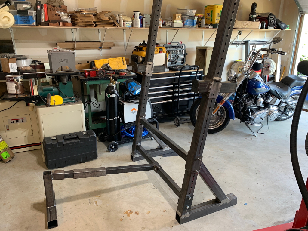
Holes are then drilled so that the supports are held with pins that go through the bar supports and the uprights. These can be easily moved anywhere up or down depending on the exercise. The pins themselves are 33/64″ W1 tool steel. Slightly larger than 1/2″, and slightly smaller than the 9/16″ holes 🙂
I cut, hardened, and tempered the pins myself.
I cut an additional bar the same length as the lower cross member and welded a piece of square tube to each end that fits over the large uprights, and then cut one side of them off so that it can be put onto the uprights, or removed, without having to slide it up off the tops. This is the adjustible support that the back of the bench seat will rest against.
Also in this photo is an 11″ long piece of 2.5″ tube which I slid onto the bench support beam. This is a critical piece as it will support the whole adjustable seat apparatus, which is arguably the most challenging bit of this project. the seat needs to slide back and forth on the bar depending on how you have the seat positioned.
To start, I cut another piece of the same tube that will be welded onto it. This will also get a flat cap welded on top.
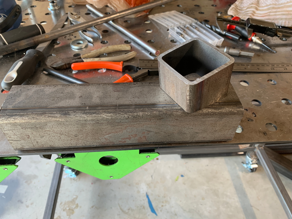
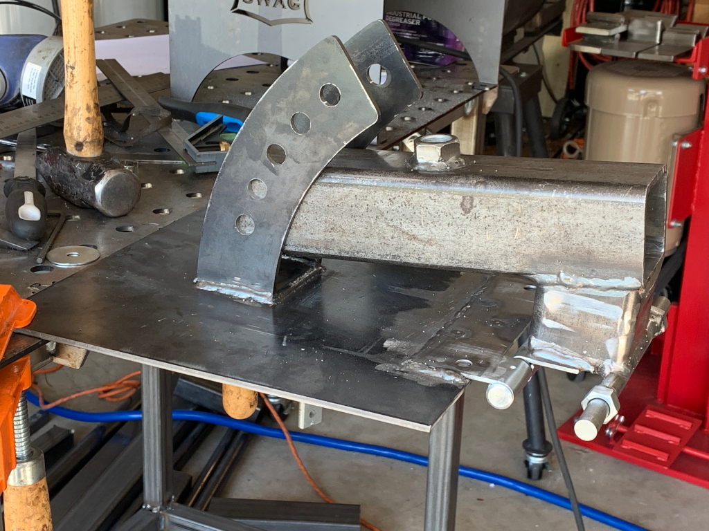
To support the bench back, I ground a recess/ledge into the top corner of the cap and welded on a length of 1/2″ steel round bar. Next, I drilled out a pair of 1/2″ nuts so they slide right onto the bar, set them the correct width, and welded them to the bar. The bench back is bolted to a pair of 11 gauge 1×1″ square bars, through which I drilled 1/2″ holes, and these then fit onto the 1/2″ bar. The nuts act as stops to prevent the bench from sliding back and forth on the bar.
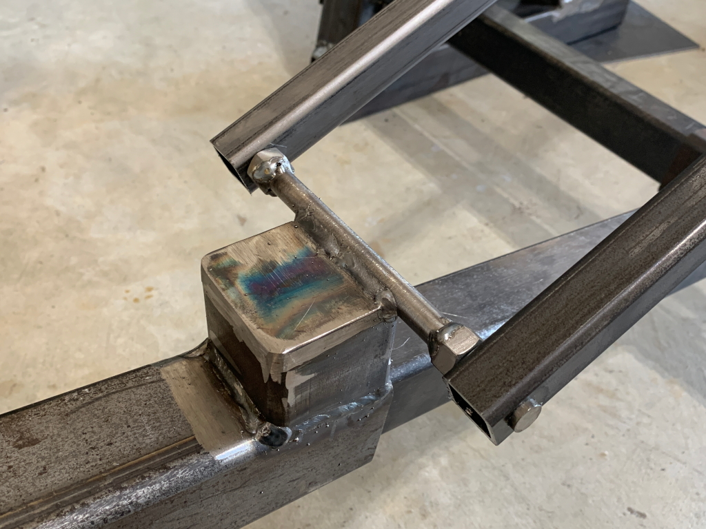
This rig is the pivot/hinge for the seat back rest.
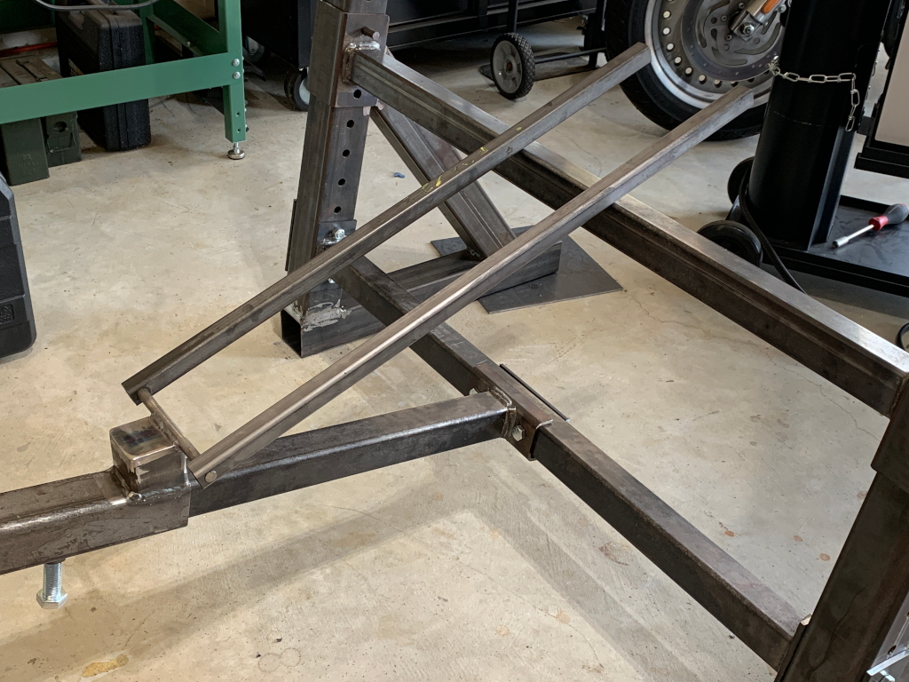
The adjustable angle seat depends on curved supports so it can be set to any angle as appropriate for the exercise being done. Flat, incline, decline, etc.
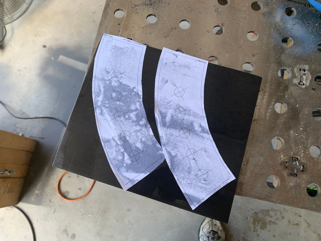
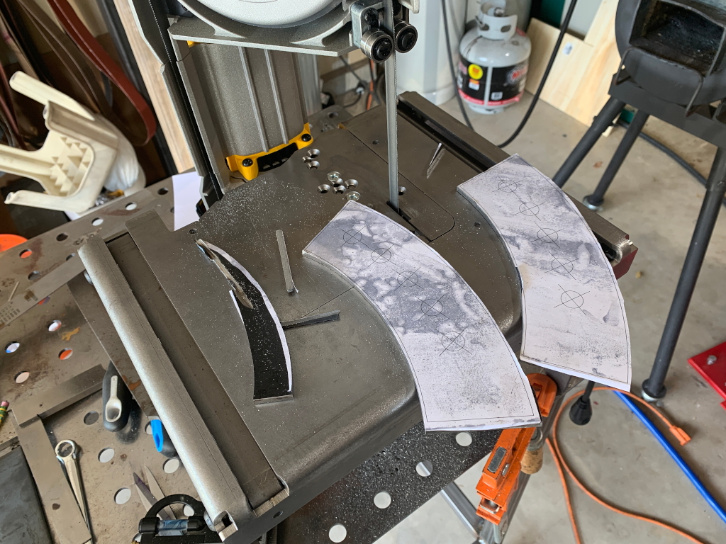
I used a 3/16″ steel plate from which to cut the supports. This will make more sense as you continue reading. I printed these paper templates from my CAD program so they are precisely the correct shape for this functionality and the holes are positioned exactly where they need to be
Cut out on the band saw
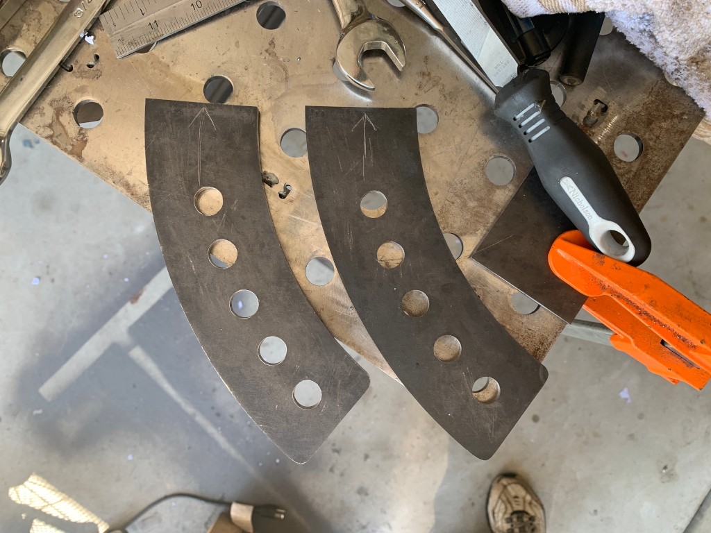
Then drilled out, and shaped on the belt grinder
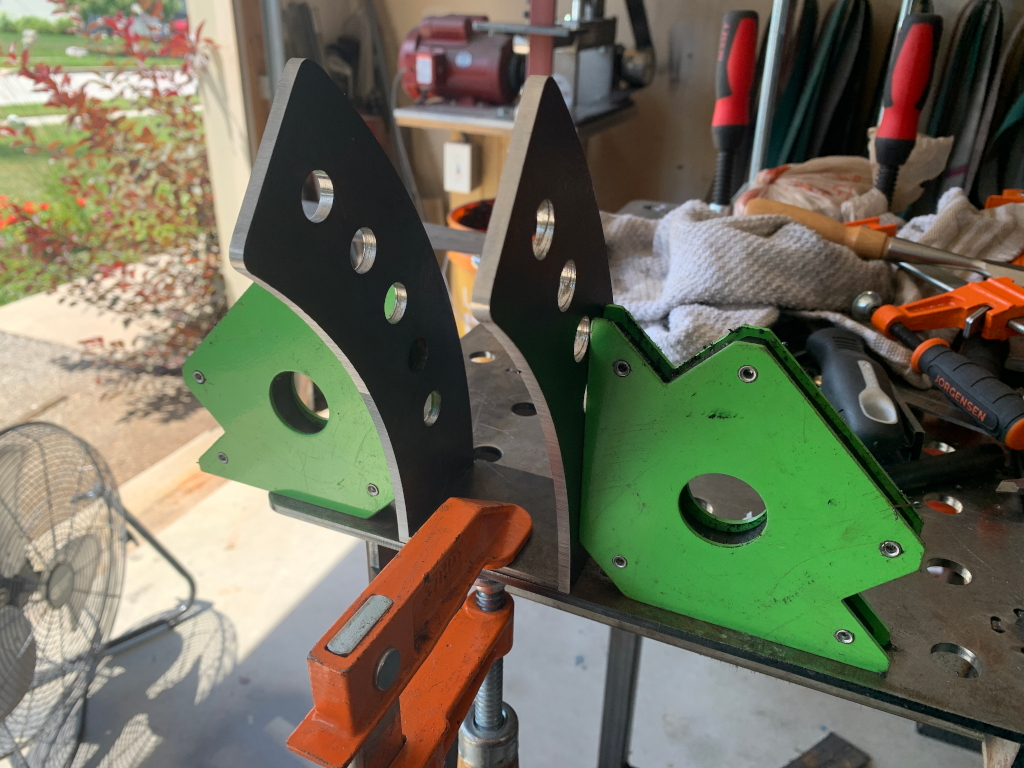
I used a pair of welding magnets to align them perfectly while welding them both to a base plate
Which was in turn welded to another 3/16″ steel plate which serves as the base support for the seat itself. Again I missed a couple pix here, but I welded the steel base plate to a big hinge. The way this works is that if you continued the curve of those supports around to a full circle, the pin in the hinge would be dead center of the circle.
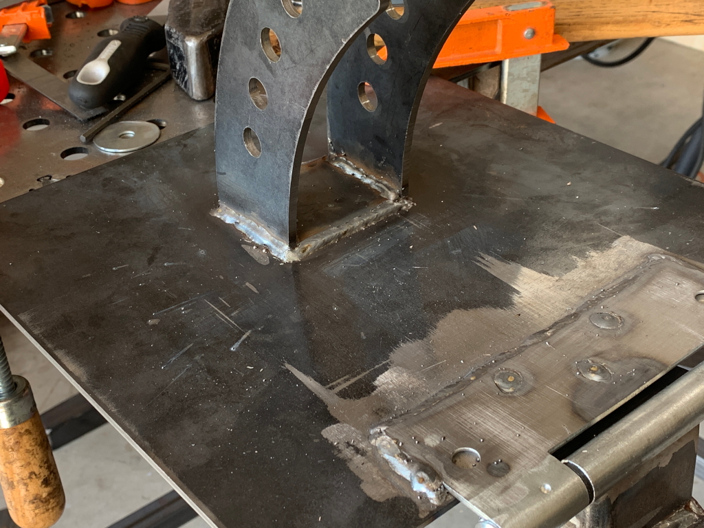
The relationship between the supports and the hinge is crucial because the holes in the supports need to align with the holes that will be drilled through the 2.5″ tube the whole seat apparatus is welded to. When the seat is raised or lowered, the next hole in the supports needs to still be aligned with the hole in the 2.5″ tube. This bit was stressful for me 🙂 Unlike the rest of the bench which moves in various normal X, Y, and Z axis, this part moves and functions in a rotational axis and in order for all the holes in the curved supports to line up with the holes drilled in the square tube, the center of that rotational axis (the hinge) needs to be placed the exact same distance as the radius of the circle around which the holes are drilled in the supports 🙂
Even a couple hundredths off would mean the holes wont line up when you raise up the seat, and just the act of welding it can cause things to move by that amount.
Frankly if I wasn’t secure in my sobriety, stressing about this one piece might have pushed me off the wagon 😉
OK, not really, but it was pretty stressful 🙂
I think at this point the concept of how it works, and how the curve of the supports relates to the location of the hinge, is fairly clear at this point. It took a bit of adjusting to get it right, and a lot of clamping, checking, moving, re-clamping, re-checking, etc, before It was spot on and I could weld it in place.
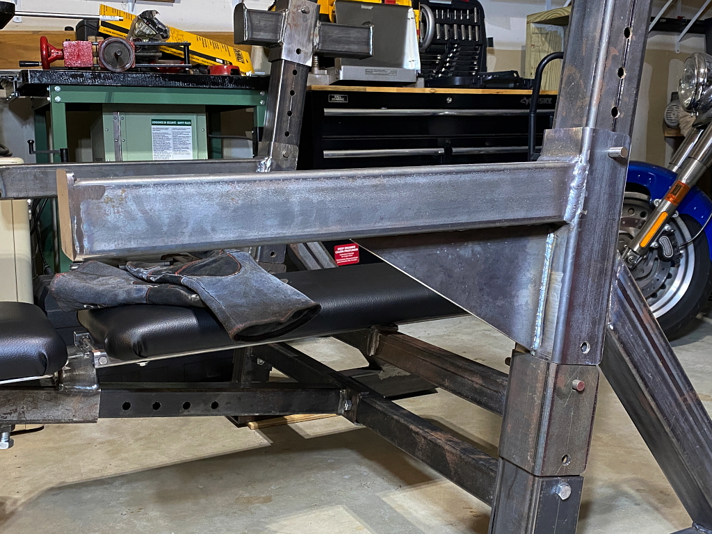
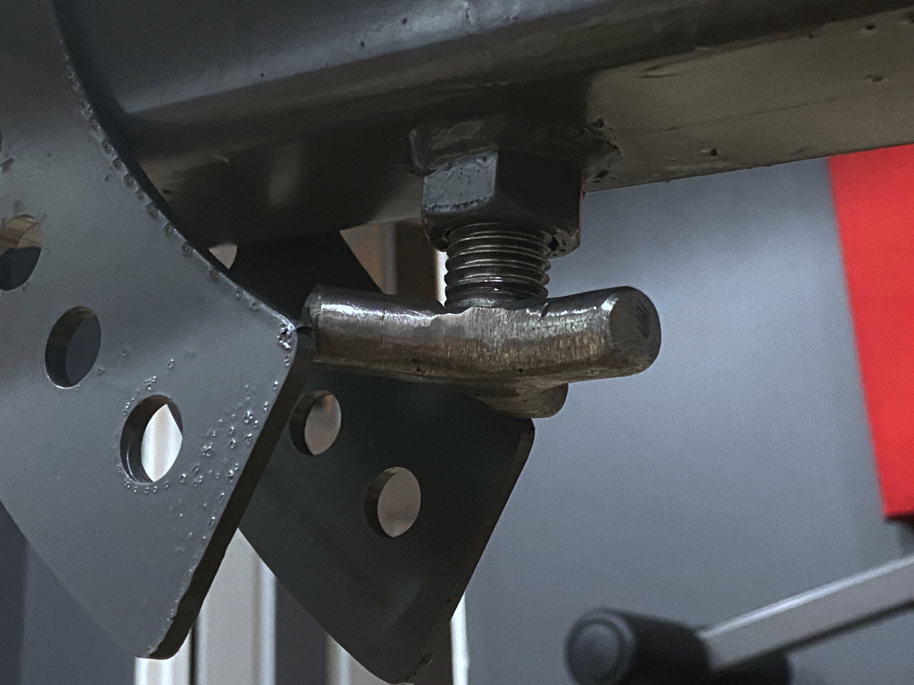
Also, I drilled a 1″ hole through the underside of the 2.5″ tube and welded a 3/4″ nut to it. This is for a locking bolt. This lets you clamp the seat rig in place after you position it. ITs not really essential to its function, and really only serves to stop any rattle between the beam and seat rig. I hate shit rattling 🙂
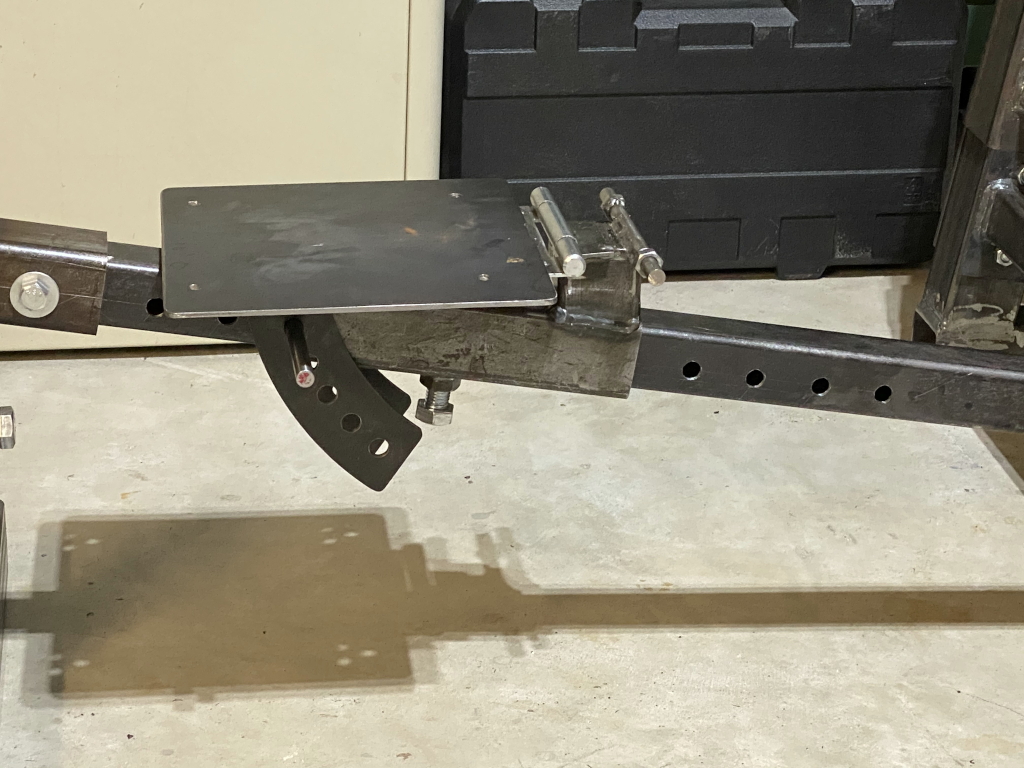
This photo essentially shows how it all works. As you can see, the whole thing can slide up or down the beam, and the seat can be raised or lowered to different angles, and a pin goes through the whole thing to lock it all in place in any particular configuration, and the 3/4″ bolt just clamps it rock stable.
For the upper end of the back rest I welded a couple guides. These just keep the top end of the seat from wanting to move side to side, especially when its fully upright, as with doing shoulder press.
Again, not really necessary to the function, but it adds to the overall stability and I like that.
Here you can see the whole seat and backrest apparatus.
So to jump back, you can see these next things in some earlier shots, but theres no explanation for them so I’m covering that here.
Theres a couple places where a smaller tube that passes through a larger tube. The seat base, which is welded to a 2.5″ x 2.5″ tube, and this slides back and forth along a smaller 2″ x 2″ tube that goes through it. The larger tube is locked in different positions by a steel pin that passes through both tubes. The pin prevents it from sliding anywhere, but it still has some play even with the pin through it, and I wanted to be able to clamp it down so that once in a given position it could be clamped firmly in place. The other location is the base at the foot of the bench which also has a 2.5″ x 2.5″ tube thats vertical, and the leg apparatus slides into the top. Both these things then need to be firmly clamped so they are very solid with no wiggle.
Initially I wasn’t sure exactly what the best way was, but my solution in the end was very simple. I wish I could take credit for the idea, but I stole it from assembling my welding table legs only about a month earlier. 🙂
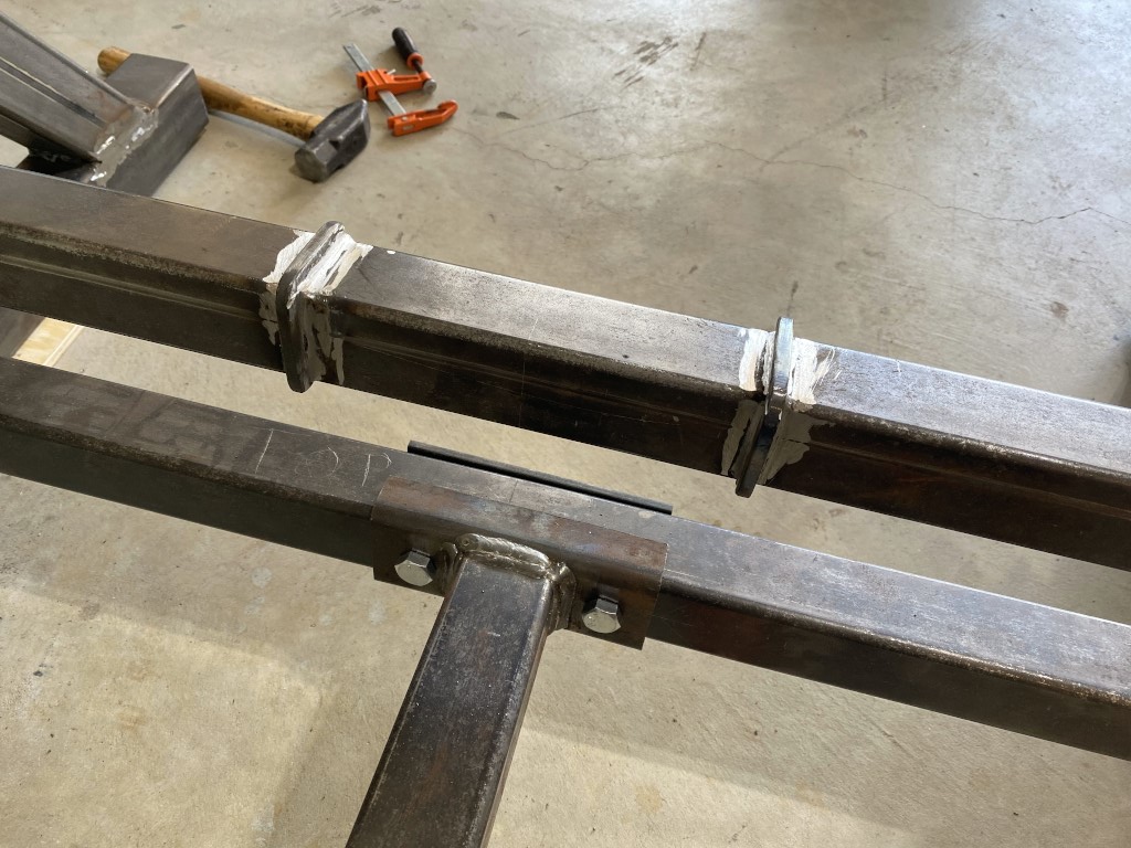
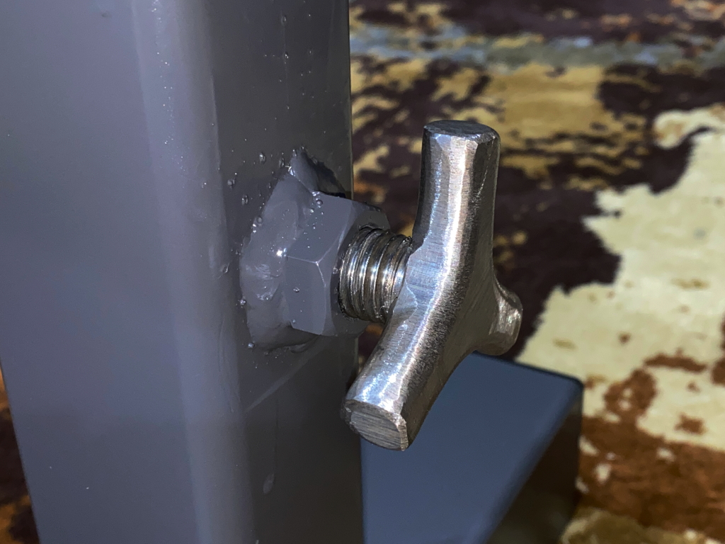
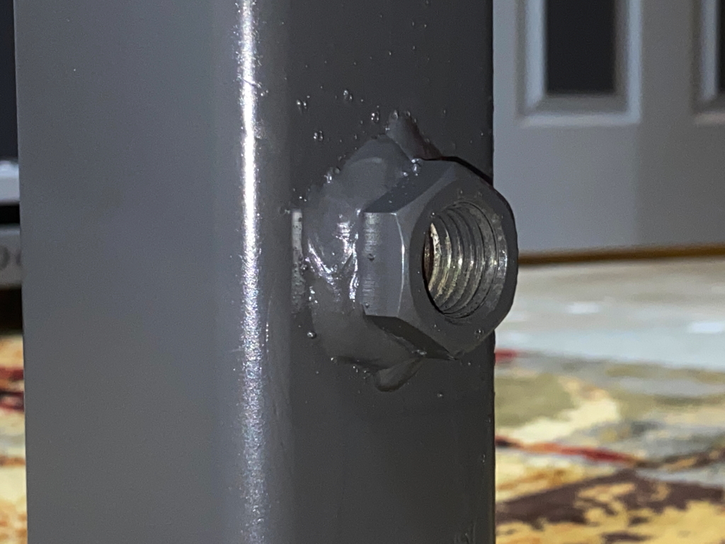
On both of the larger tubes I drilled a 1″ hole through one side. I purchased a couple of 3/4″ nuts and 3/4″ hex-head bolts. The nuts were a slightly larger outside diameter than the 1″ hole, so I positioned them so that they just covered the hole, and then welded them on. Thats it. Now I can just screw the bolt in, and it will come up against the smaller tube inside and basically push it hard against the opposite inside of the tube.
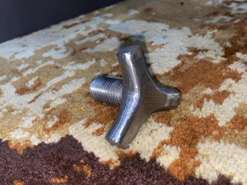
To make it slightly more user friendly, I welded a one inch long piece of 1/2″ round bar to 3 sides of the hex head, and then used my bent grinder to shape it into a handle. Its not the prettiest knob in the world, but you can torque it down pretty tight just with your hand, and thats all it needs to be able to do.
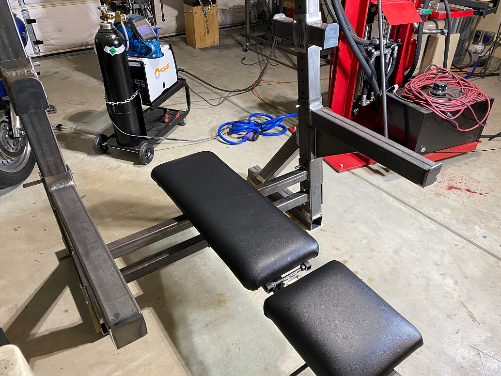
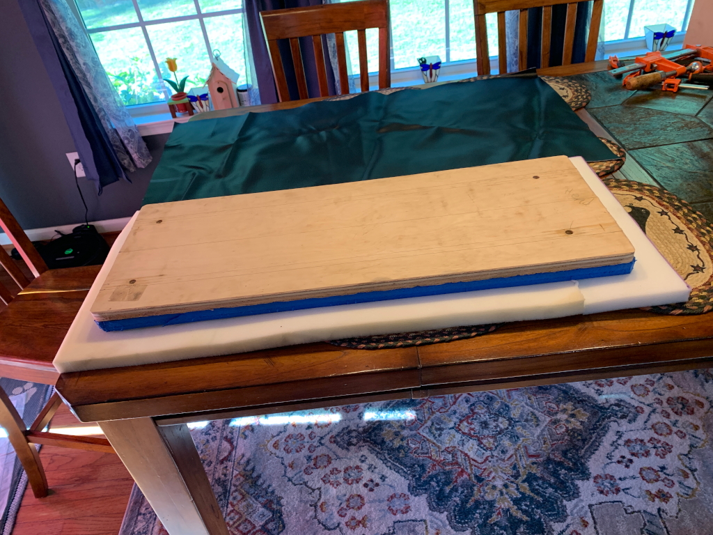
Of course that doesnt look all that comfortable, so heres the actual seat and bench back. I used 3/4″ plywood for the core of both seat and backrest. I drilled holes in both and inserted 3/8″ T-nuts from the top. 3/8″ bolts can then be threaded into them
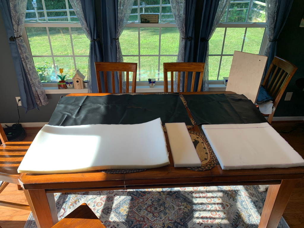

On top of the plywood I glued 1″ extremely firm, high density foam (the blue layer in the photo), and on top of that a layer of slightly softer foam.
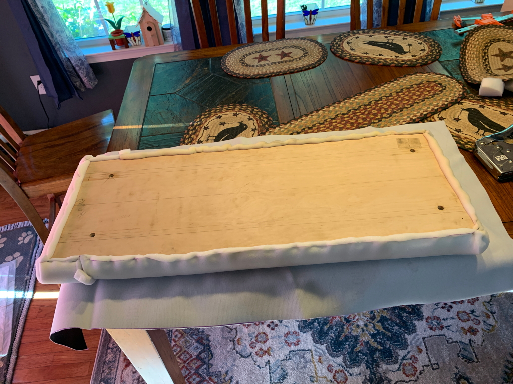
Then stretched a layer of marine grade vinyl upholstery over that. One or two staples hold it in place 😉
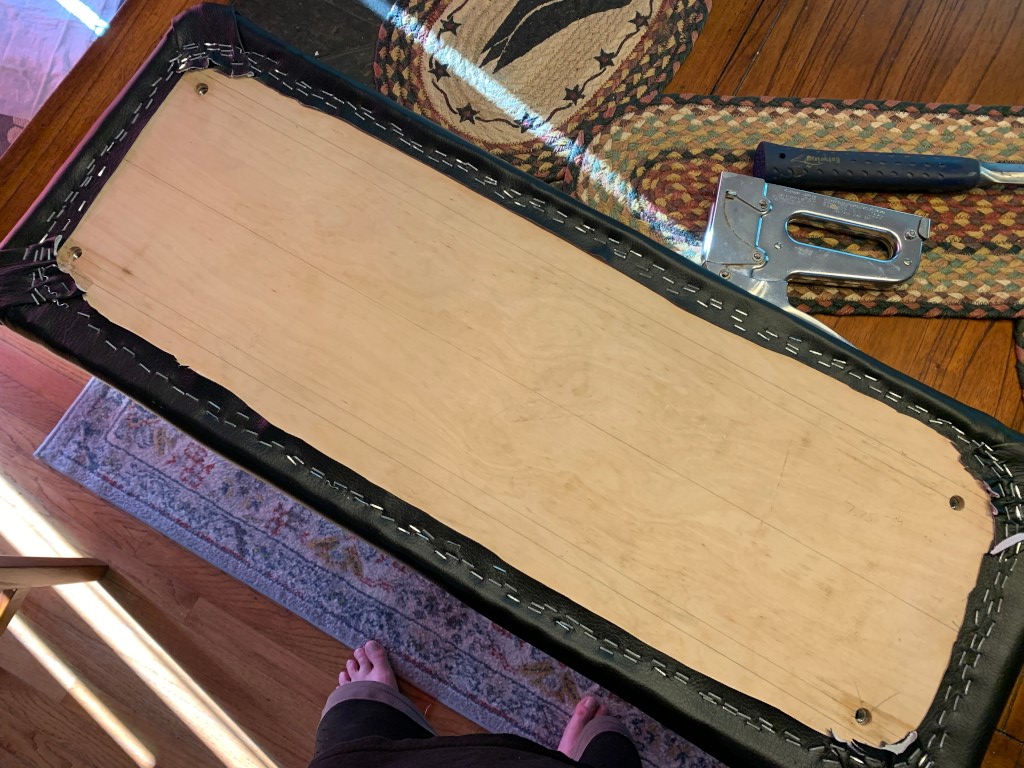
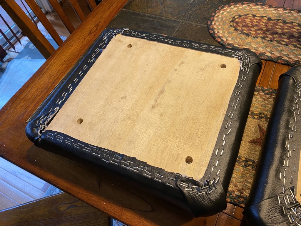
The goal here is a comfortable, but firm bench. You dont want it too soft or you wont be solid and stable while holding heavy weight, but you also dont want it too hard.

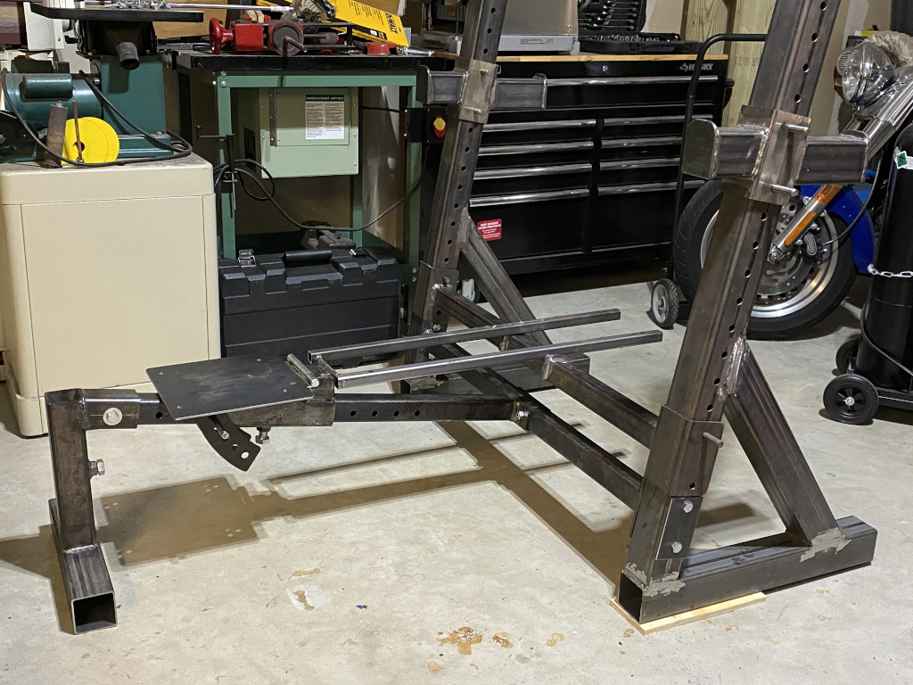
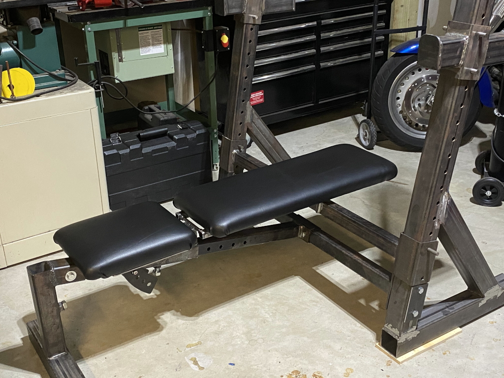
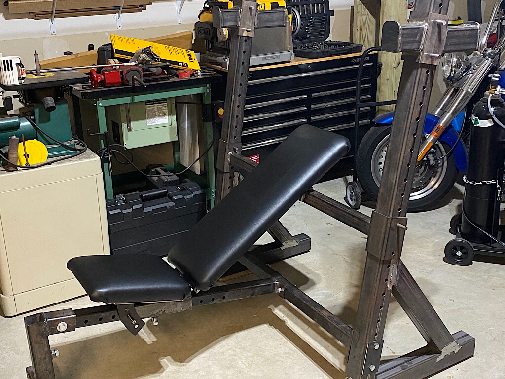
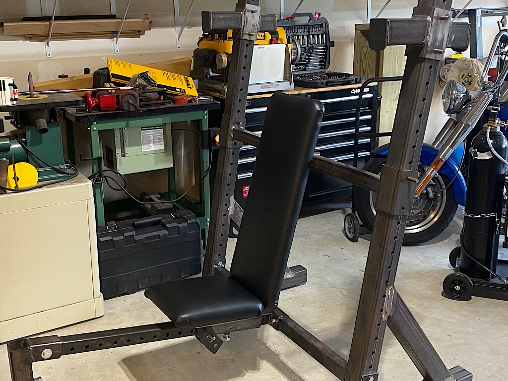
All bolted on. The next 3 photos show a few possible positions, As you can see, the seat slides back and forth on the beam, and the support cross-member is raised or lowered to set the angle of the back rest, and the bar rests are raised or lowered to set it where its needed for any given position. with 2″ increments for all parts, the number of possible positions is huge. Any person, regard less of their size, can find positions that work for them.
For safety sake, I also built a set of bailout bars. These are for working out solo (no spotter). You set these at a height that doesnt interfere with your reps, but if you fail and cant get the bar back up onto the rests you can set it down safely and can slide out from underneath it. I built these even stronger than the bar rests in case you cant set it down as gently as you would like. In addition to being fully welded, I used a piece of 1/4″ plate as additional support underneath.