You may note that I say “cut” as opposed to “drill”. Not a mistake. Overall I need to have over 200 very precisely located hole in various parts of the bench. This is is all 11 and 7 gauge steel. Not only would I go through a pile of drill bits, but I would lose some accuracy. Instead I use a TCT hole cutter. TCT=Tungsten carbide tipped”. It has a very short centering drill bit. The dimples in the steel left by the center punch, combined with the rigidity of such a short bit, will center it and prevent it from wandering. Drill bits wandering from where you want them is a very common issue when drilling steel. Once centered, the carbide teeth on the cutter part make short work of the A36 hot-rolled steel. Its a bit more costly than a standard drill bit (not much though) but the precision and longevity are well worth the few extra dollars.
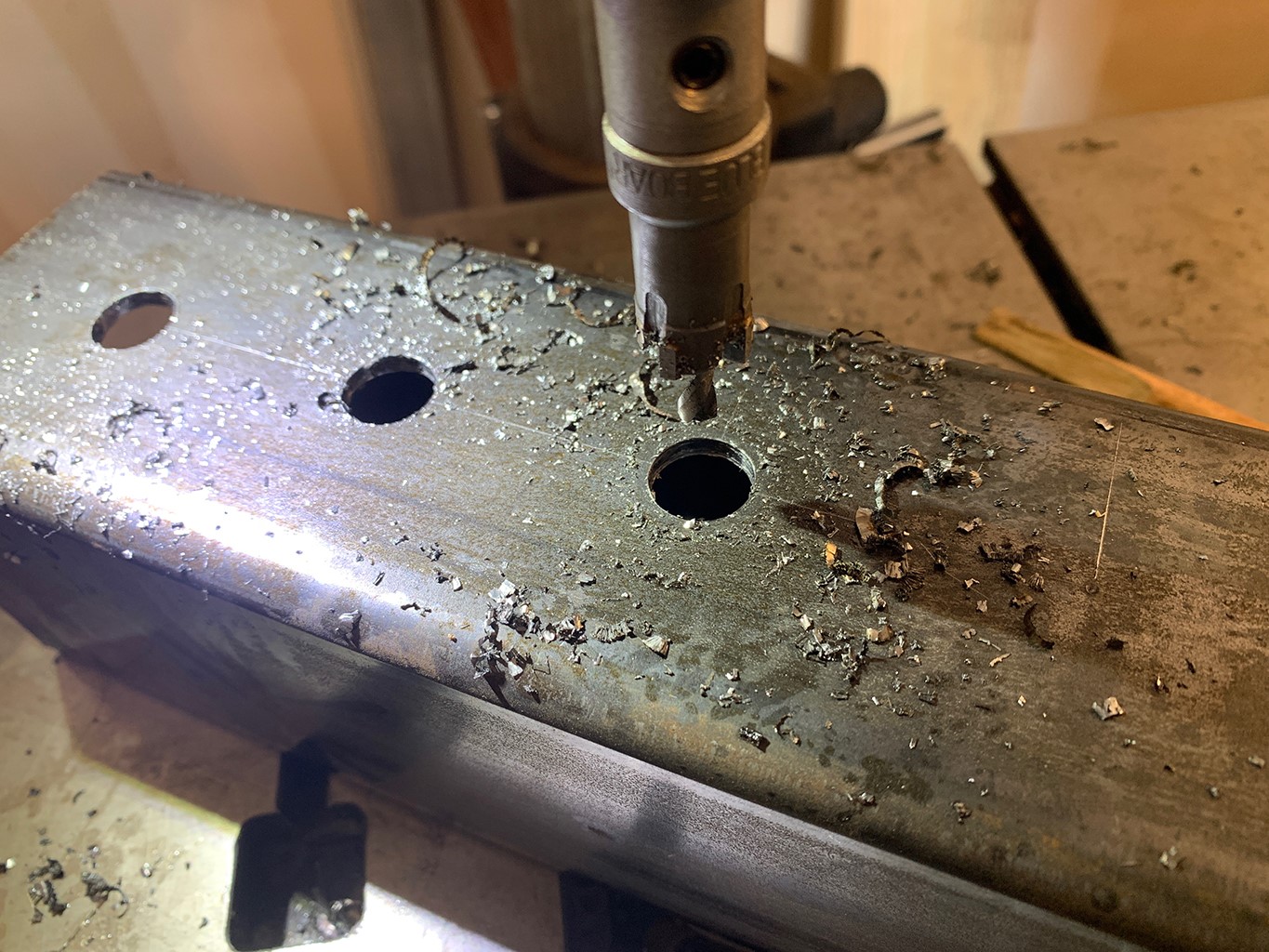
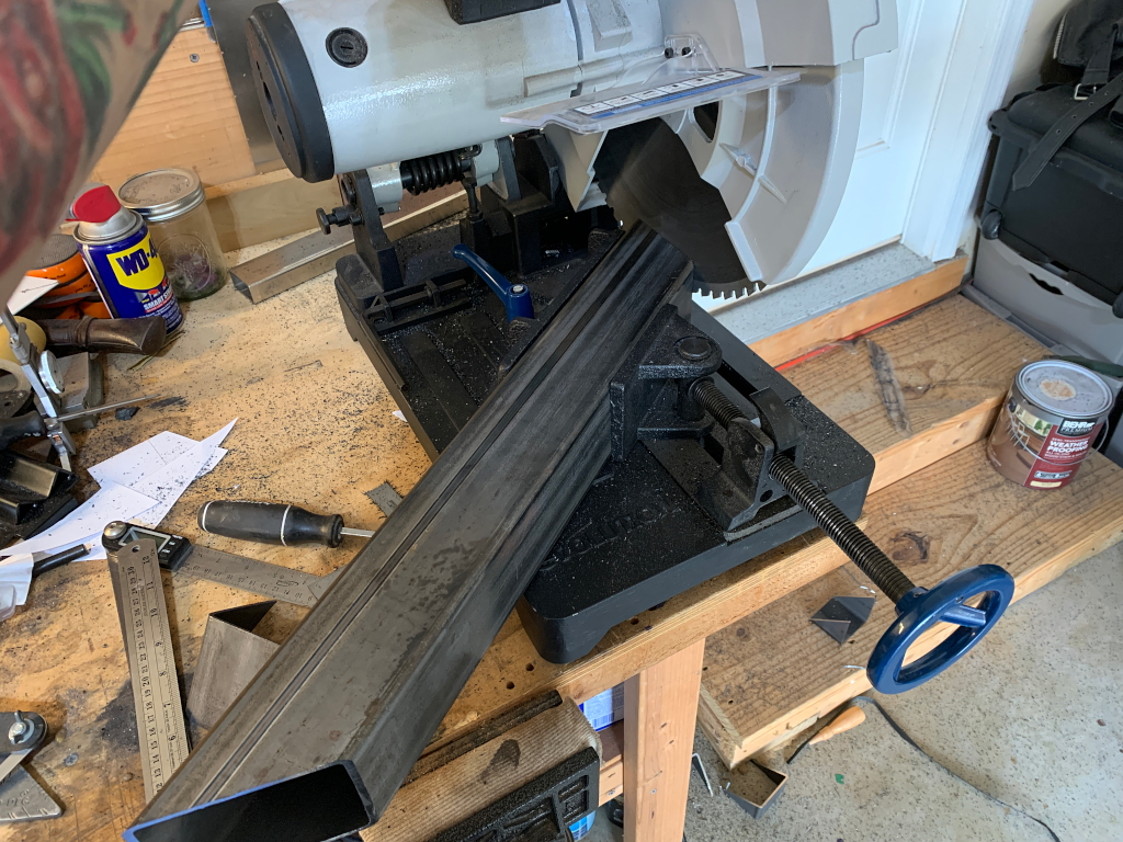
Here it is in action. I did this over 200 times. It didnt make for a terribly exciting couple days…
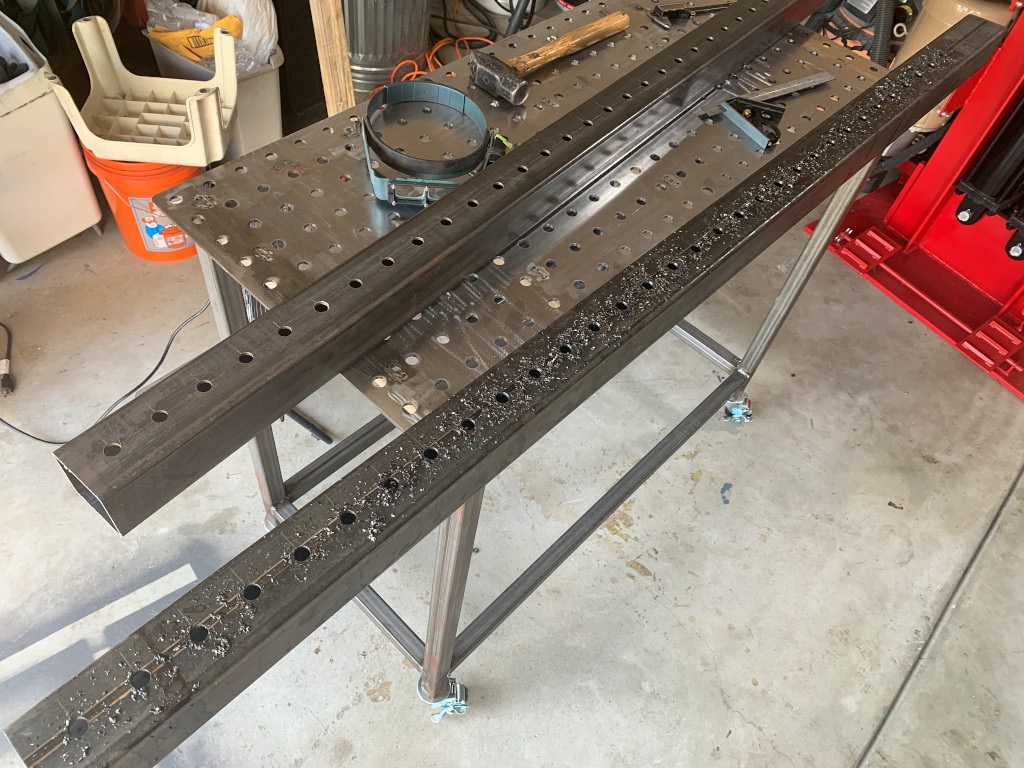
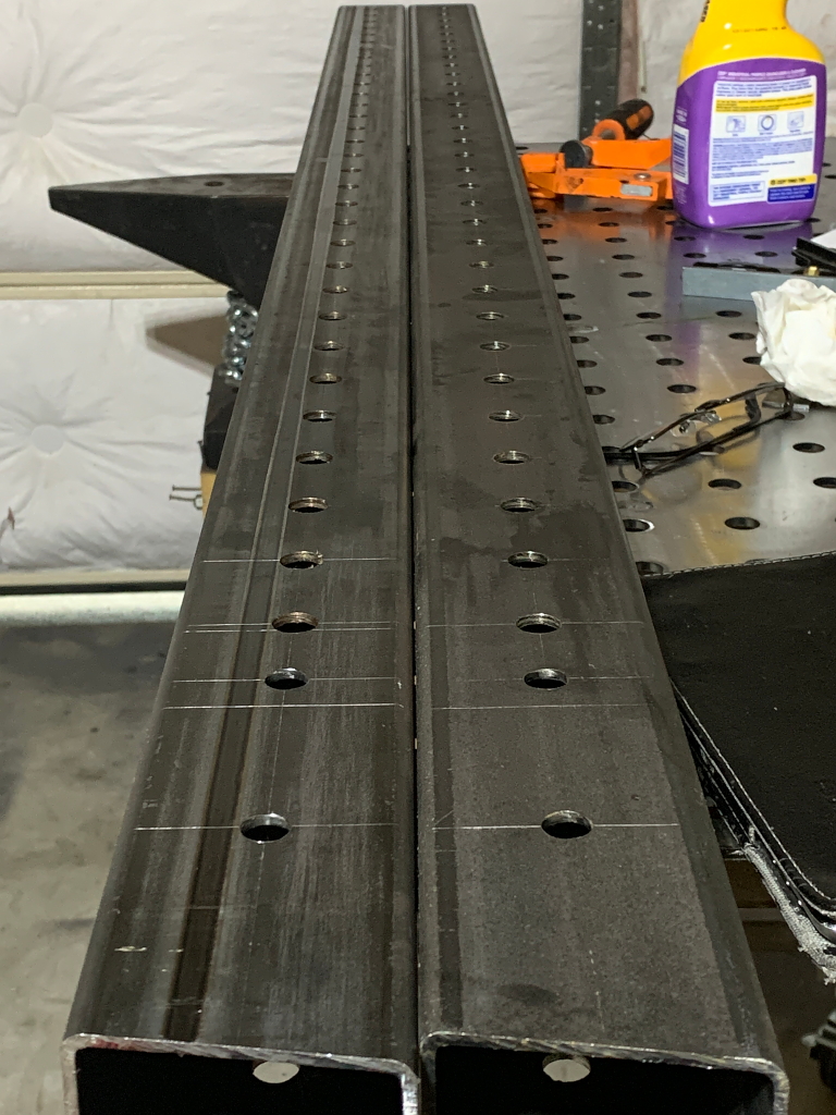
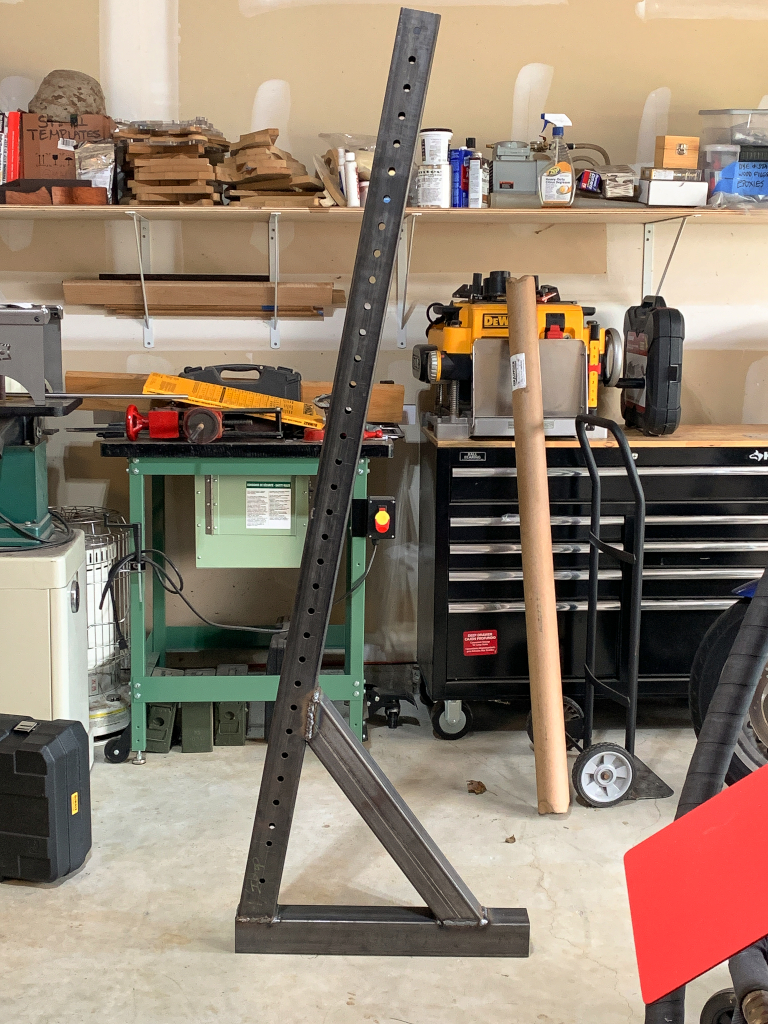
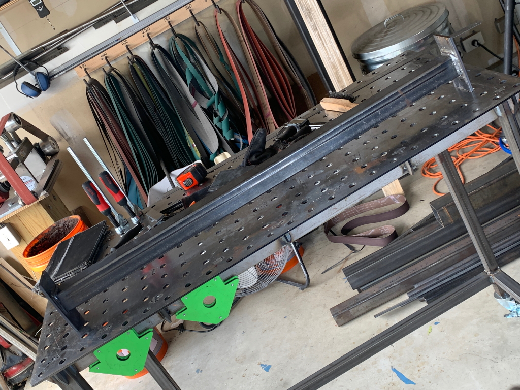
And the final result. This is one side of one upright, about 32 holes. I think theres about 212 total holes to drill for the entire build, so I have a long way to go 🙂
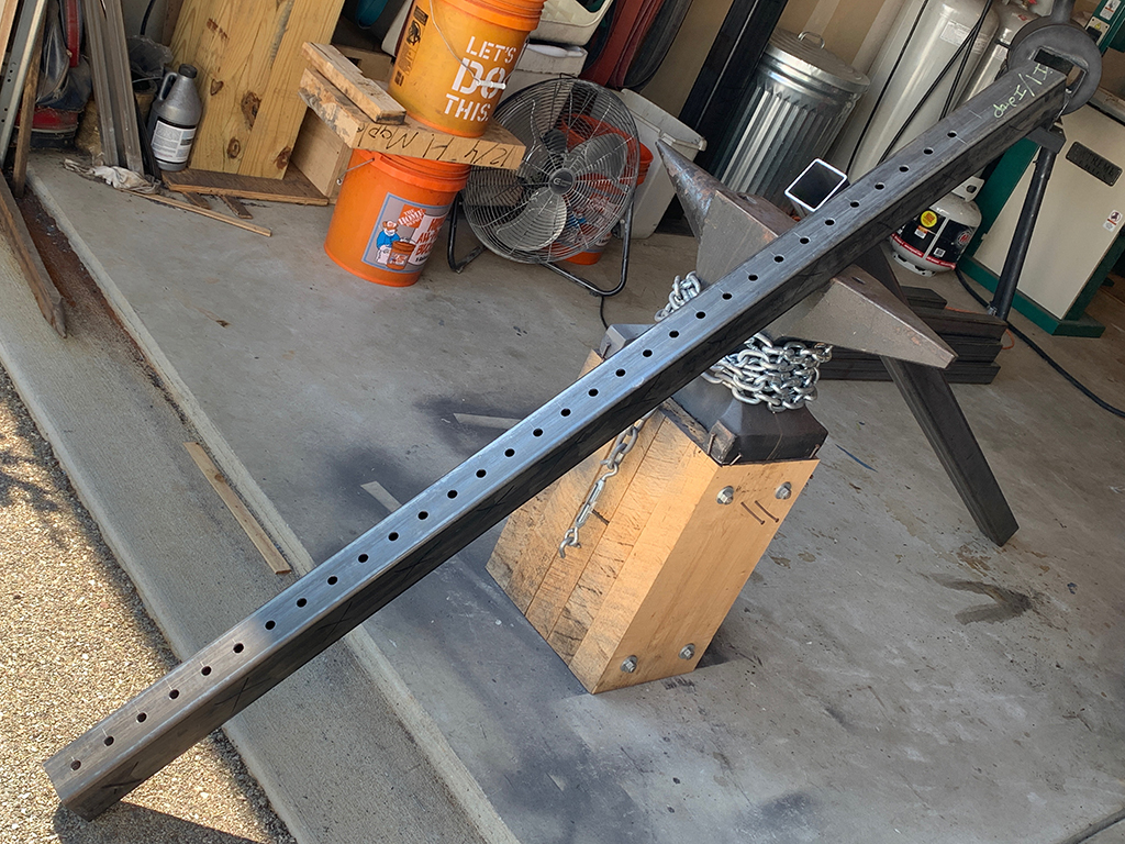
Unlike all the other holes, the last 8 are 1/2″ and are for the bolts that hold the uprights to the cross member. With these complete, the uprights are finished and ready to weld to the base and angle support.
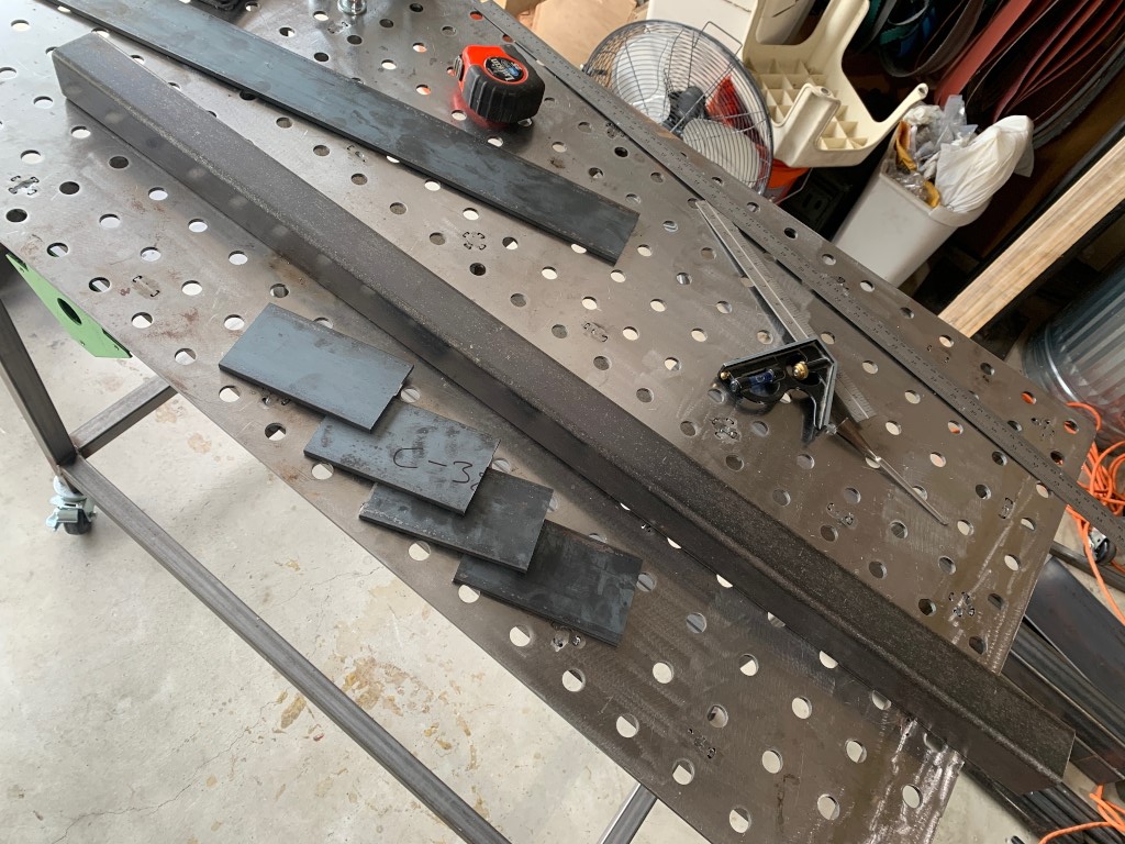
Holes all drilled, now cutting the base and angle braces.
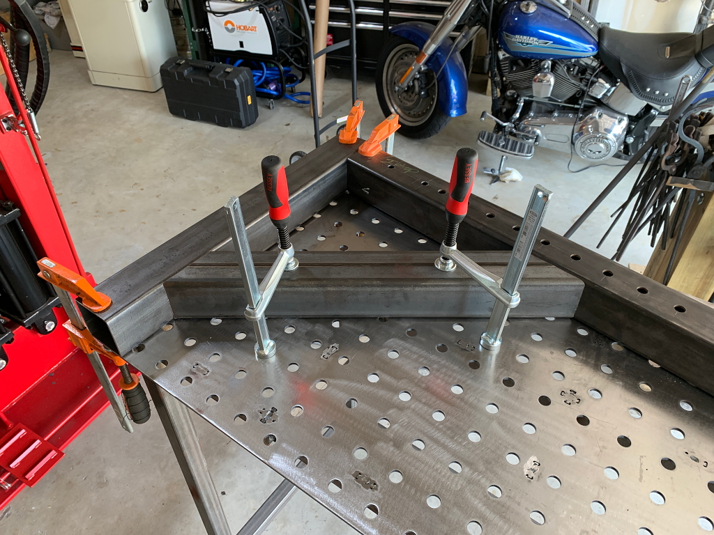
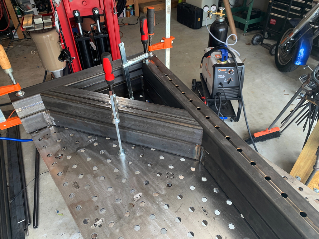
Clamp them together on the welding table in the exact positions and angles needed. In this position I do a series of tack welds just to keep everything aligned exactly right. This is because weld beads shrink as they cool and can pull things out of proper alignment, so the welds need to be done in the right sequence so that things stay aligned exactly as intended.
One upright all welded up. Will need to grind down the raised weld beads somewhat before painting. This is just for appearances sake. Some of the beads were pretty ugly, mostly because I dont have vast experience welding, however they are absolutely strong. Its interesting to view the welding on this job in a linear way and note how the beads got nicer looking as I progressed through the job.
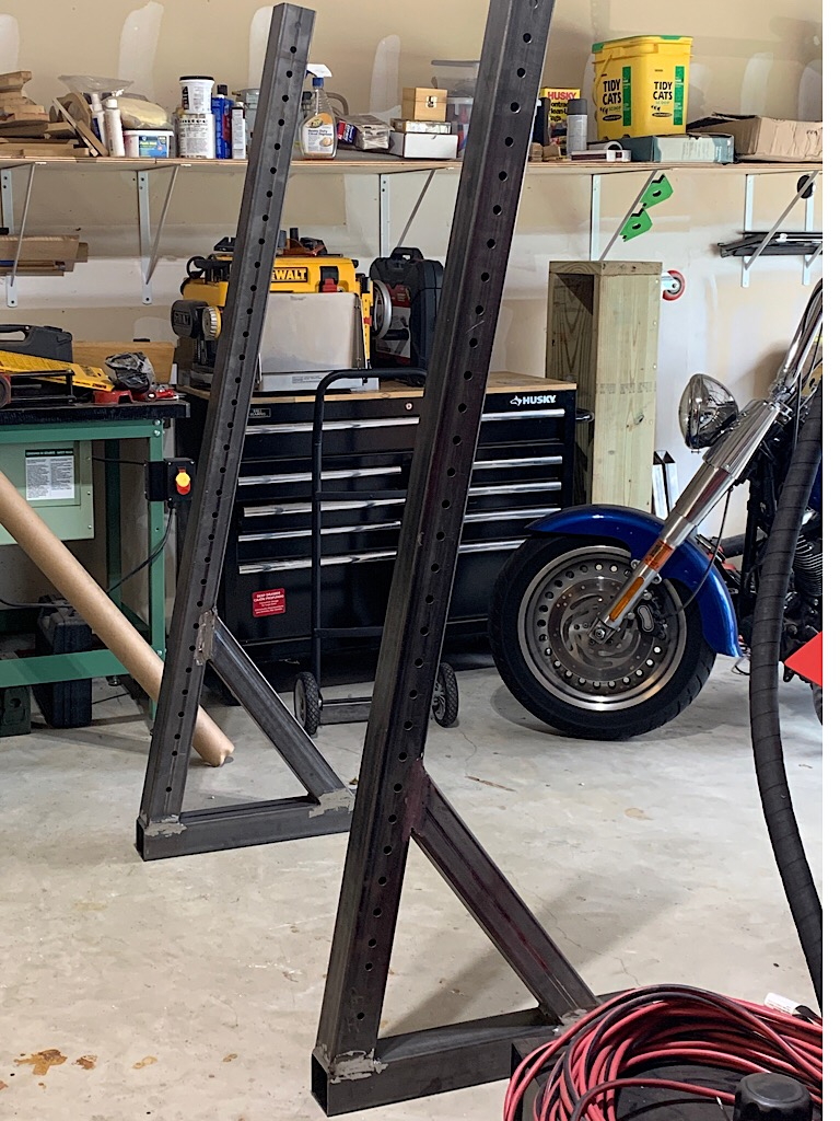
I used the first upright as a template and clamping caul to make sure that the second upright is aligned exactly the same as the first one. This is important 🙂
Looking good.
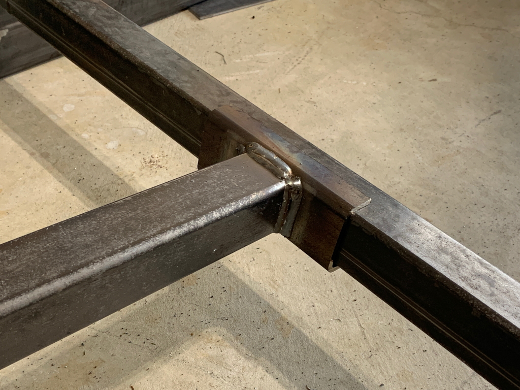
Next, the two uprights need to be connected to each other. I cut a piece of the 2×2 tube to the correct length, and 4 pieces of 1/4″ bar to serve as the clamping plates
Two of the small plates I welded to the bar, one at each end, taking care to make sure they were aligned perfectly with each other. This is important because these keep the uprights square and plum to each other. Once welded, holes are drilled through all 4 plates
1/2″ bolts are then used to connect the uprights together with the cross-member. The remaining two small plates are outside end plates which allow me to crank the bolts very tight without crushing the upright tubes.

I neglected to take pix when welding up the foot of the bench, but you can see clearly enough. A piece of 3×3 for the foot, and I used 2.5″ x 2.5 upright on the foot form an upside-down T which acts as a stable base for the foot of the bench. The large open ended upright will accommodate the leg apparatus later on. I used another piece of the 2.5, cut at the appropriate angle, forms a socket for the bench support beam coming up from the cross bar. The bench support bar is set perpendicular to the tall uprights, so the height of that foot is designed to match the height of the bench support bar at that end. The beam fits into the 2.5″ tube, which will be drilled and bolted. The clamp at the other end is obviously temporary 🙂
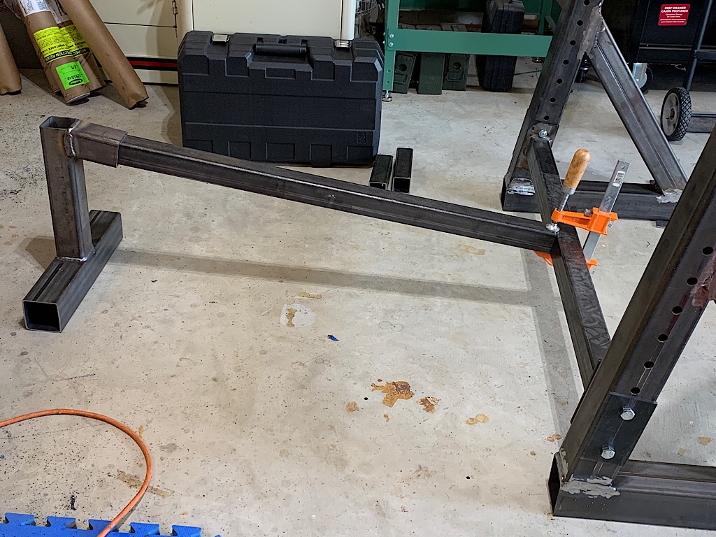
Clamp no longer needed. 🙂
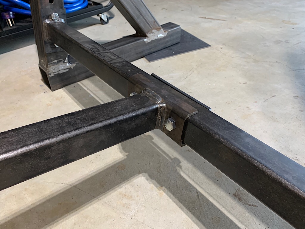
drilled and bolted. Again, I use a plate on the opposite side to distribute pressure.
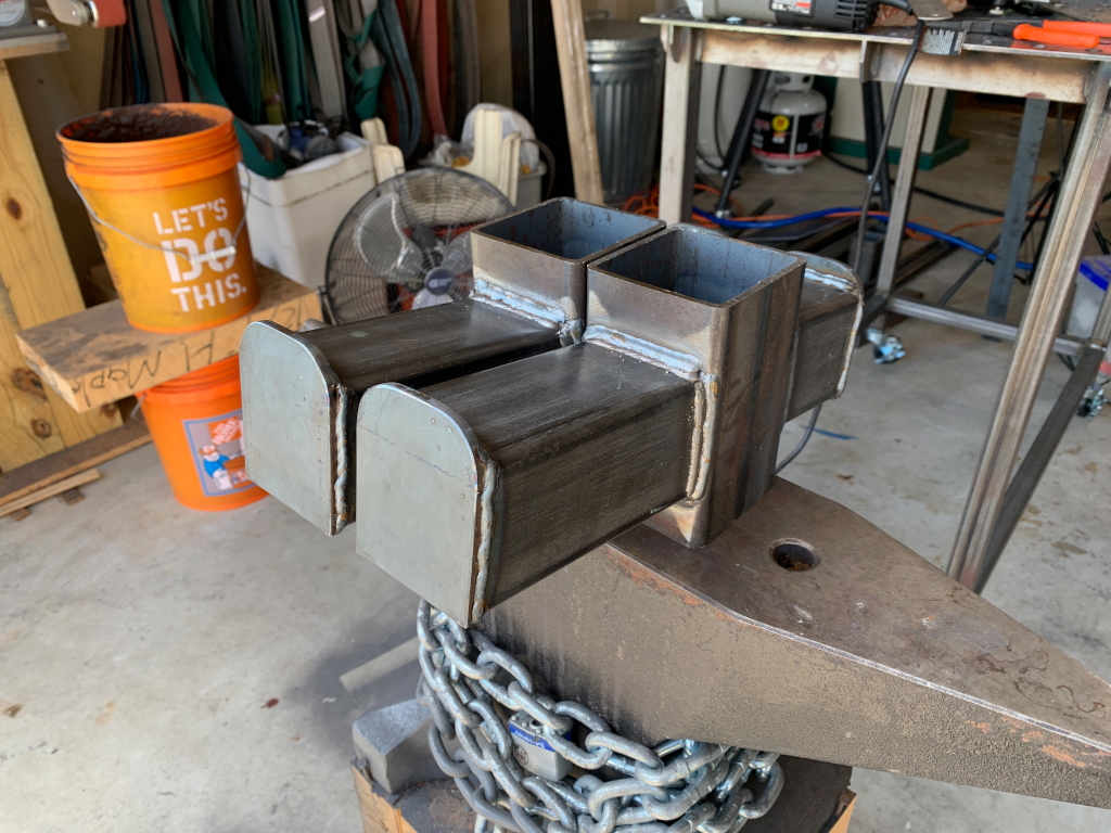
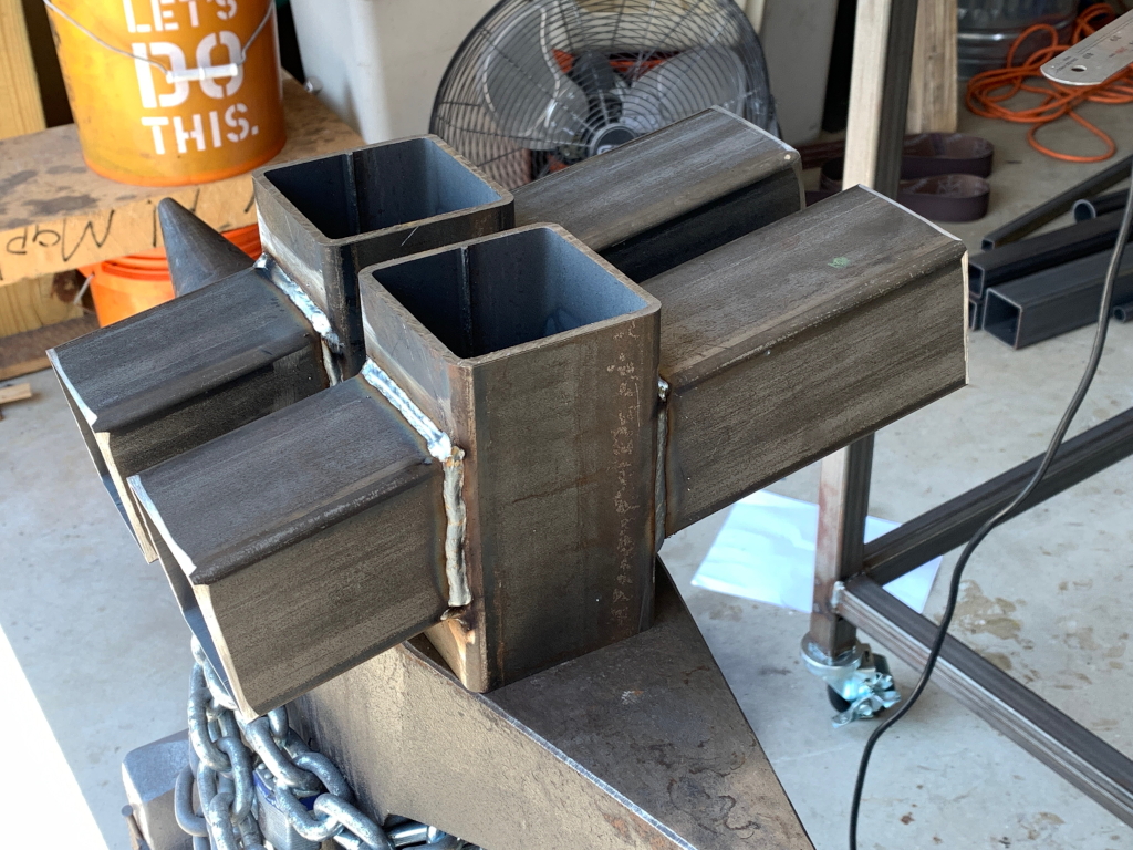
Now to the bar supports. These are made from 3 1/2″ x 3 1/2″ tube so that they fit over the uprights. The supports are welded to these front and back and will serve both bench pressing on one side, and squat rack on the reverse side.
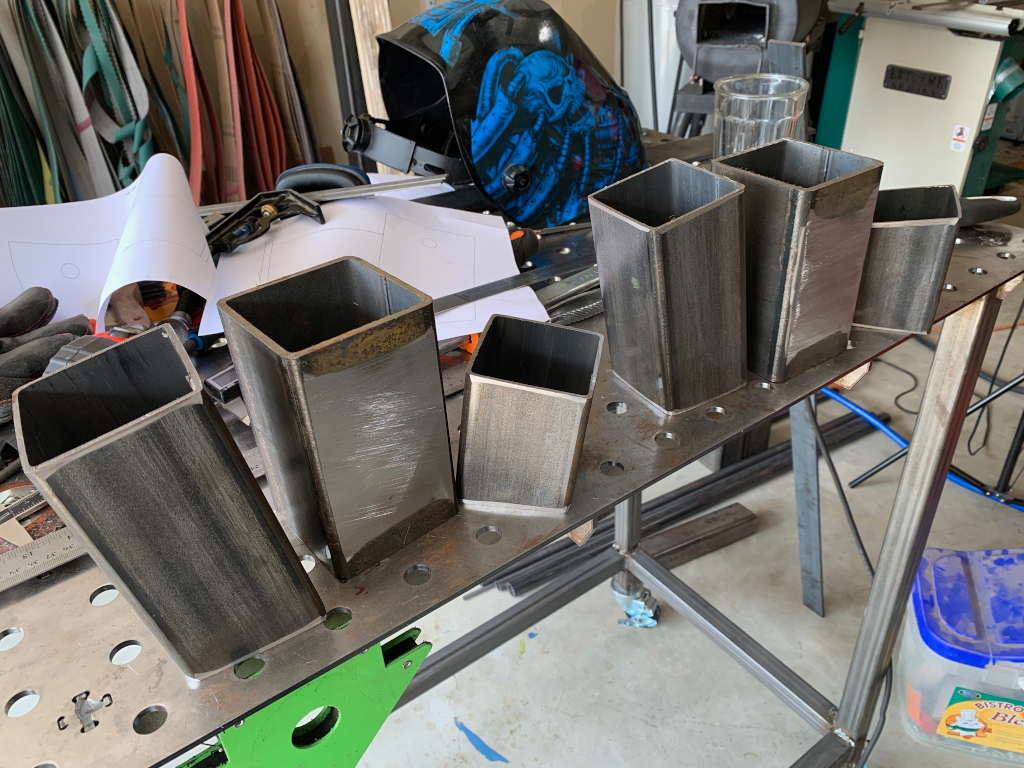
Welded up. Worth noting how much better my welds are looking at this point, since now I’m “warmed up” 🙂
End caps welded on to stop the bar from rolling off and crushing peoples skulls 🙂